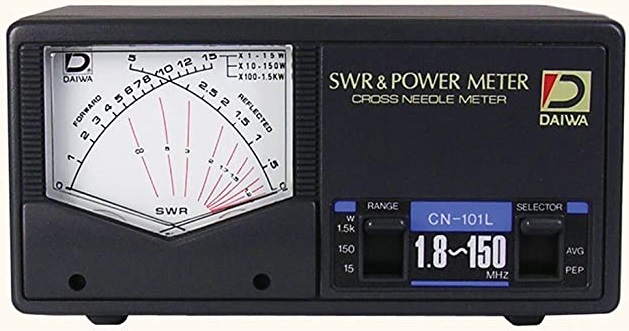
Daiwa CN-101L PEP power measurement.
I have been using this SWR-bridge for many years.
The cross needle scale indication is easy to read.
However, with ssb in the PEP mode, the power measurement is misleading. The indicated transmission power is much lower than what is actually outputted. This is mainly due to the aggressive character of the SSB signal versus the slow response of the gauge needle.
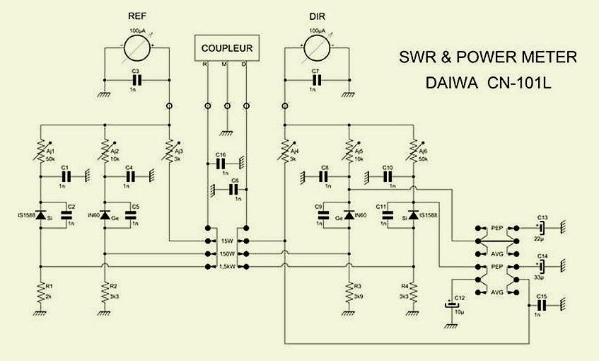
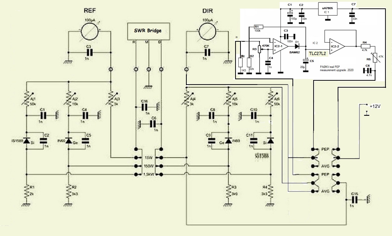
In the electrical diagram you can see that an attempt is made to compensate for the needle inertia by stabilizing the forward signal from the swr bridge by means of electrolytic capacitors C12, C13 and C14. This attempt is not very successful.
PEP measurement update.
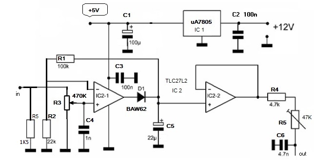
PEP diagram.
PEP circuit integrated in the SWR meter with wiring to the PEP switch contacts.
Description:
In PEP mode, the forward signal is connected to the input of opamp 1. The output of opamp 1 charges capacitor C5 through diode D1. C5 discharges through R1 and R2. Discharge time ~ 2.5 seconds. The signal on C5 is buffered by opamp 2 and connected to the forward gauge.
Installation:
Remove C12, C13 and C14.
Cut some tracks around the switch. See picture below.
The freed contacts of the PEP switch are used to connect the input and output of the PEP circuit to the SWR bridge and power gauge. The 12V supply voltage of the scale lighting is connected to the PEP circuit via the third freed contact.
In the PEP circuit, this 12V is reduced to 5V by means of an uA7805.
Adjustments: set the SWR device to the 15 Watt position and transmit a 15 Watt tune / cw signal to a 50 ohm dummy load. With potentiometer R3 you set the output of opamp 1 just below saturation. Adjust the forward gauge with potentiometer R5 to a 15 watt indication.
Provided that the forward indicator is reasonably calibrated in all three power settings, the PEP measurement will also be correct in all three settings.
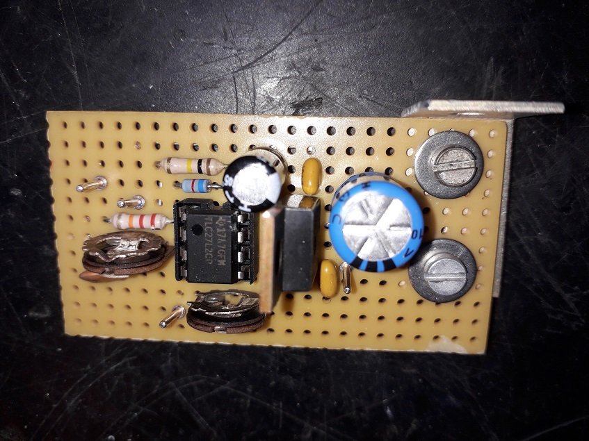
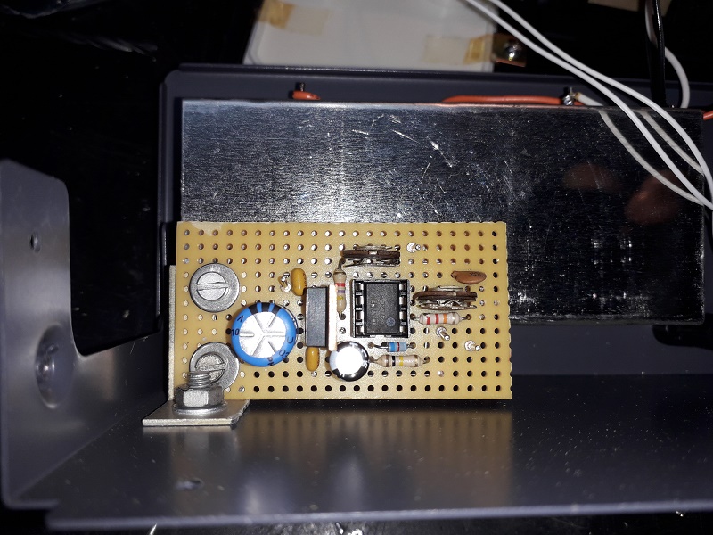
PEP circuit board
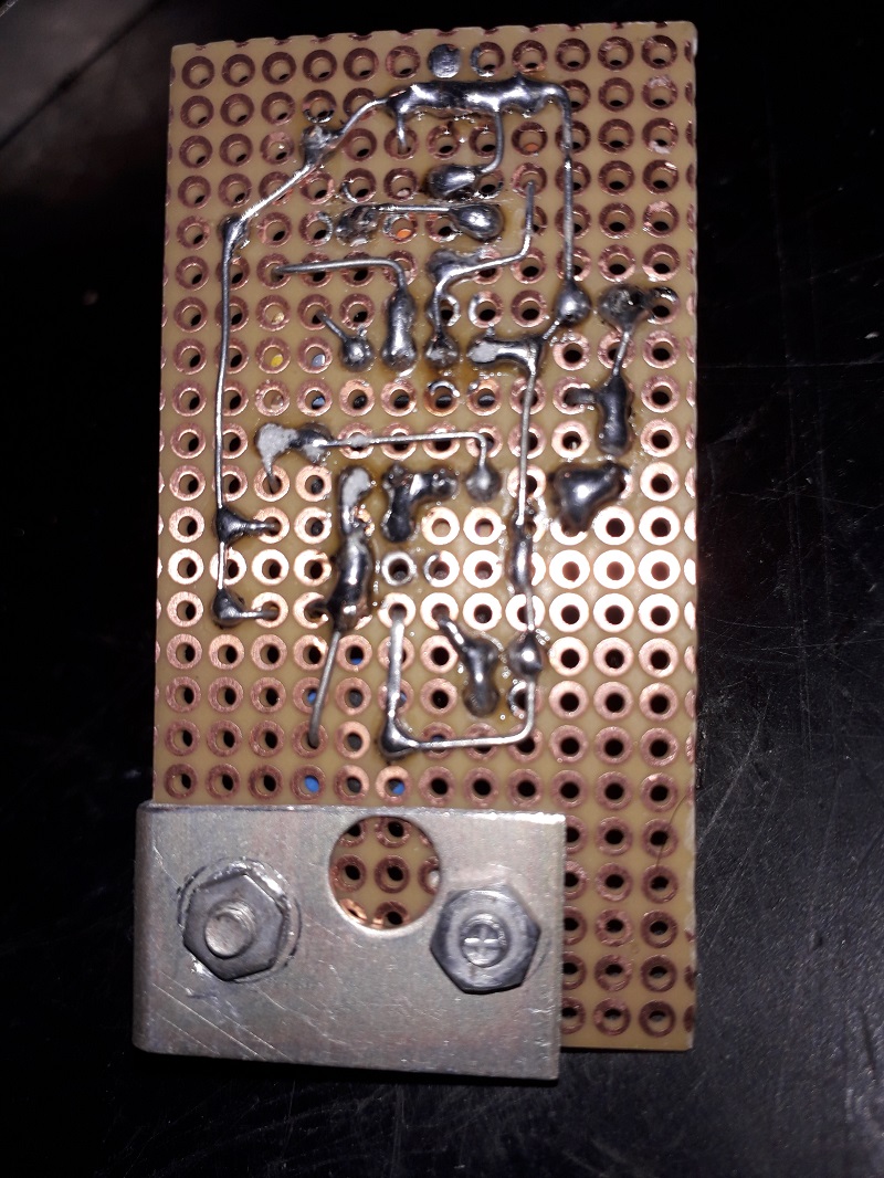
PEP circuit board track side.
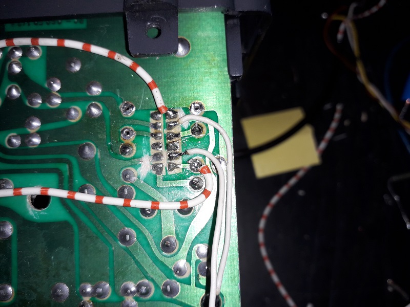
PEP switch contacts reused. !!! Several tracks have been cut to free switch contacts!