
Below some pictures of my antenna's on my previous QTH.
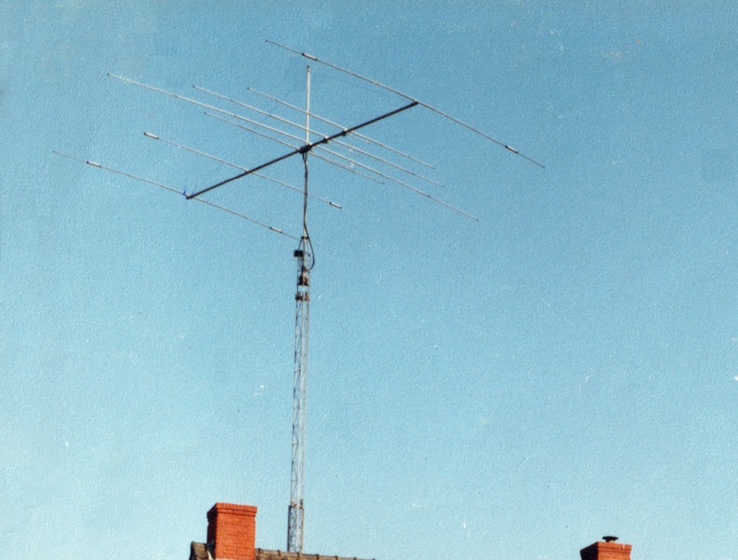
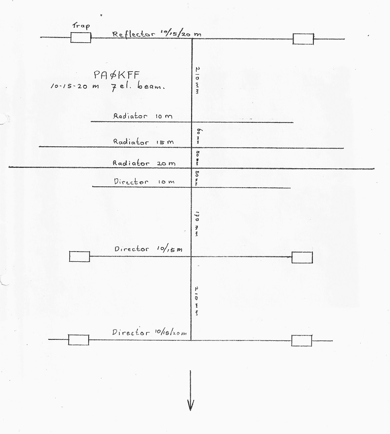
My design of a 7 element 3-bander Yagi for HF. It has 3 full size radiators. 20, 15 & 10 meters.
This improves SWR, being close to 1:1 across each band. (In compare with trapped radiators.)
It also eliminates the risk of a burned-out trap in your radiator while turning up the power to get that DX station, hi.
Coupling is done by gamma match. Band is chosen by means of a coax relays. Only one coax going down to the shack.
Director/reflector traps are Fritzel made.
3-el on 20 meter, 4-el on 15 meter and 5-el on 10 meter.
The boom is 7,5 meters long (~ 24 feet). See MyBeam for original drawing.
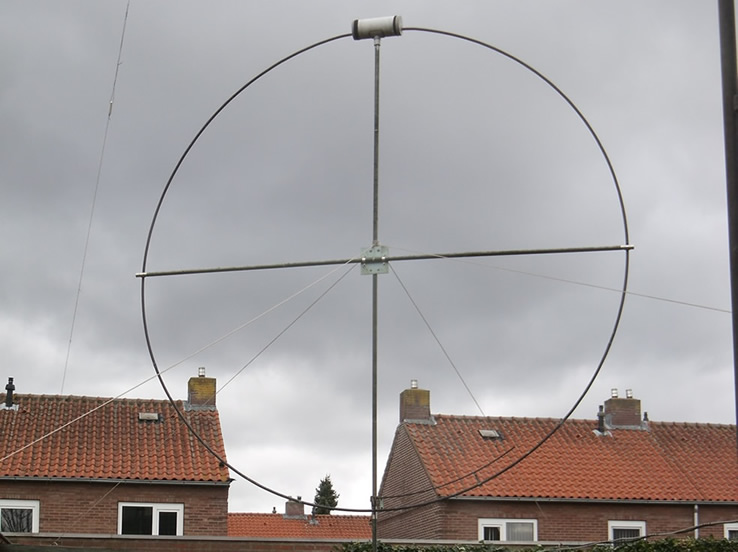
A magnetic loop. 4 meter in diameter. Covering the 160 & 80 meter band.
More on this antenna see Projects.
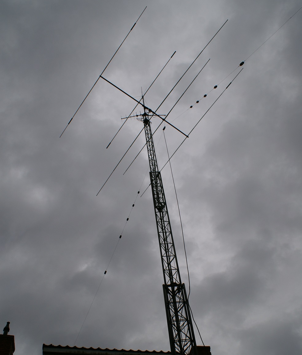
Above: my Versa tower with a trapped Inv-V antenna for most HF bands.
Due to lake of space on my property I can't span a full size dipole horizontally. Even a full size Inv-V was a problem.
But a Inv-V with several coax traps would shorten the overall length and after some calculation it turned out that I needed 5 traps in each leg.
Another advantage is that the trapped Inv-V would be in resonance on the WARC bands (12, 17 & 30m) and 40 and 80m.
A coax trap is a tuned coil/capacitor combination which are in parallel.
The coax windings form a coil, the core and shield form a capacitor.
At resonance this trap has a high Z and will block (trap) signals from passing through. The antenna 'looks' shorter.
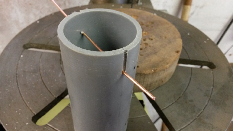
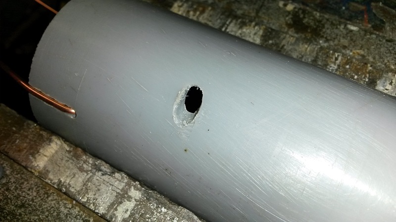
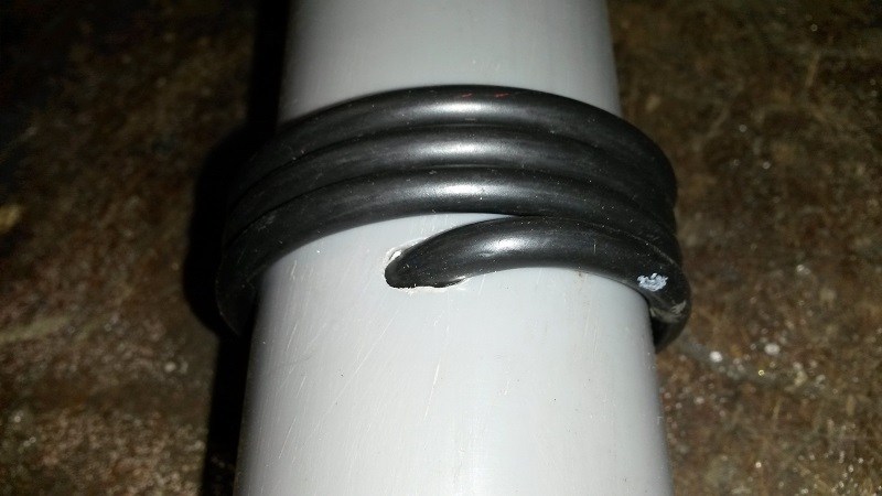
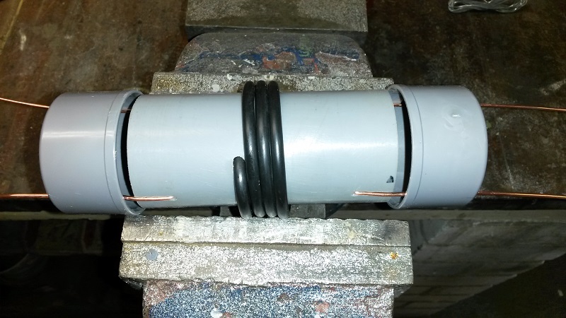
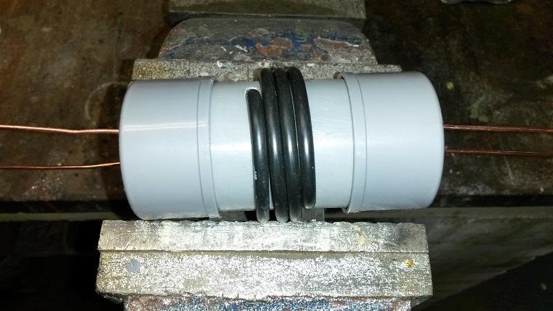
I use Ø 50mm PVC tubing with end caps. The coax windings are placed in the middle closely
winded and where the coil begins and ends a hole is drilled in the tube. Strip the coax and push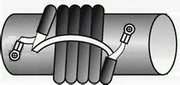
the end through the drilled holes.
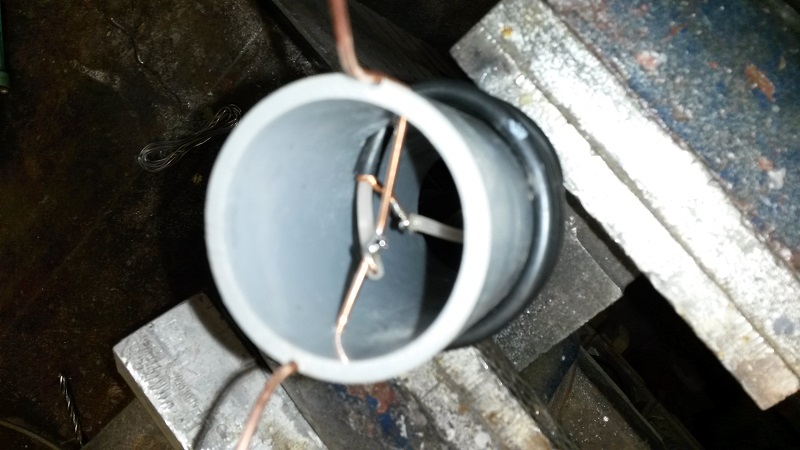
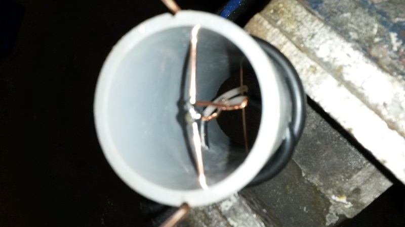
In the tube the core of the coax on one end is connected with the shield of the other end.
You end up with one loose core an one loose shield. These loose ends are the
'input' and 'output' of the trap. To keep the dipole symmetry, trap pairs should be installed symmetrically. Rule of thumb; connect center conductor of trap coax toward center of antenna.
There are trap calculation programs on the web. I use this one, called Coax trap. Wire diagram
My coax traps for 10, 12, 16, 30 and 40 meter
on 50 mm PVC tube with RG-58 coax:
- 24.89 - 24.99 Mhz (12m)
5 cm - 3.1 wind.
- 18.07 - 18.17 Mhz (17m)
5cm - 3.98 wind.
-
14.2 - 14.3 Mhz (20m)
5cm - 4.81 wind.
Tuning can be done with a grid-dipper or antenna analyzer.
-
10.1 - 10.15 Mhz (30m)
5cm - 6.35 wind.
-
7.00 - 7.10 Mhz (40m)
5cm - 8.59 wind. Always measure the resonance frequency!
One of my 7 Mhz traps in mid air. 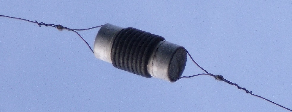
Over the years I build several traps, with different constructions, looking for a waterproof and mechanical strong solution.
This design (pic above) will last for years without problems. The coax is closely winded and enters the inside tube via precisely drilled holes exactly on the point where the coil winding ends. Drill size equals coax outside diameter. Hold the drill in a certain angle so that the coax goes through more easy, following the curve of the windings. (See pics below.)
Trap parts: - PVC tubing 50mm OD 44mm ID. The length depends on the type of coaxial (pf/m) and the number of windings.
- Two PVC 50mm caps
- 1 meter solid core copper wire 2.5 mm2
- Hard PVC glue.
Below some pictures (links) showing how I build a trap.
- drilling for the 2.5 mm2 copper wire
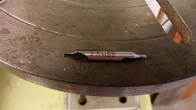
- tool for milling a groove (center drill)
- milling the groove with a table drill, with the PVC tube in a drill vice, moved by hand
- copper wire position. Copper wire tightly bend into the grooves
- caps Two holes in line with the grooves of the PVC tube
- wires through caps
- coax holes. See the angle of drilling.
- winding the coax
- soldering-1 See wire diagram above. Note. Mark coax center conductor side!
- soldering-2
- assembling and glue the caps. Apply enough glue to the inside of the caps and on the outside of the tube.
- glued Press the two caps firmly on the tube. Let them dry for 24 hours before use.
Also apply some glue in the holes where the coax enters the tube. Make it waterproof.
- connections bent into the correct shape.
I make two 5mm lugs and use an inox 5mm screw with washers to attach the antenna wire in between.
In august 2019 I moved to the village of Eersel. Back to the countryside. :-)
Here I have the space to hang an 80 meter delta loop between the trees. The loop hangs about 20 meters above the ground.
With a 30 meter open line, this antenna is connected to the shack. A resonant delta loop has an impedance of ~ 100 ohms. At the shack I screwed a 2:1 balun to the wall and connected it to the transceiver with ~ 4 meters of 50 ohm coaxial cable.
I cut the magnetic loop until it resonated 1:1 at 3,630 Mhz. Then it is also 1:1 in resonance in the even higher bands (40,20,10m).
The magnetic loop and versa tower with 7-elements, 3-band yagi has been dismantled with the move.
With the new delta loop I no longer need the magnetic loop, but for HF I do miss my yagi. :-(